IN THE YARD: Designing Ship Build and Transport Cradles
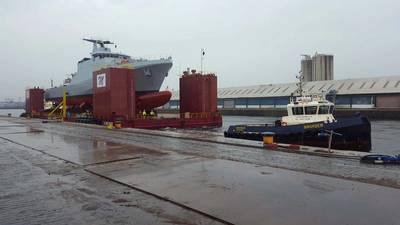
Transportation cradles are a key component in the build, transportation and launch of a ship and a suitable design can be fundamental in the success of these operations. Throughout their use they will support the various blocks and completed ship during construction, act as the interface between the vessel and SPMT’s (Self Propelled Modular Transporters) or barge, and ultimately support the ship during float off operations. The cradles are possibly the only item of equipment that will see the ship from very early stages of construction through until she is floating in the water. It is apparent that the correct transport cradle design is of the utmost importance.
At the early stages it is important to outline the design parameters and drivers. Generally, the main considerations will be steel weight and cost (which are interlinked). Keeping these as low as practically possible will of course depend on the engineering budget available. This then becomes a trade-off between the two and having a target steel weight or not to exceed (NTE) weight from the outset can be beneficial and prevent the burning of excess engineering hours.
It is not unreasonable to assume that the design of the transportation cradles will be carried out before the shipbuilding process begins. This poses its own problems in that an accurate ship weight and longitudinal weight distribution will be required as a basis to design the cradles against. Ideally, the ship will have been modelled in structural or draughting software, with weights and stiffnesses defined, allowing for an accurate weight estimate at each of the cradle locations. In most instances this will not be the case and approximation distribution methods would have to be employed. This inherently introduces some uncertainty into the weights and appropriate factors of safety should be applied. Further to this, it is important to consider that the weight of the ship may increase due to operational or design changes and it is always recommended to factor this into the initial ship weight. Overcompensating will never cause issues whereas undercompensating almost always will.
Once the weight and distribution of the ship has been adequately defined a transport arrangement can be identified which will generally involve the use of SPMT’s. The SPMT arrangement is a key factor in the design of transportation cradles and should be established prior to the commencement of engineering. Seeking the input of an experienced transport engineer to produce a preliminary trailer configuration is beneficial and gives assurance that the cradles are being designed and checked to a working arrangement. There may be a requirement with larger ships that they are built in several blocks in the build halls before being moved to a hardstand with greater space to be combined. Individual block moves and their respective trailer arrangements should be considered as before as loads into the transportation cradles here will differ from that of the full ship transportation. When SPMT configurations have been identified it is then possible to determine the locations of the support stools in the build hall and on the hard stand, and the location of the grillages on the barge (or occasionally, the ship).
Appropriate load cases will be devised to reflect the various stages of the build and transportation process. Generally, these will include a static case with the completed ship and individual ship blocks positioned atop the build stools, a case representing ship and block weighing, a case during SPMT transportation for both completed ship and individual ship blocks, and a case during barge transit to the float off location. Environmental conditions such as wind should also be considered where appropriate.
The static case when the vessel is on the build stools and during weighing operations tend to only account for the weight of the vessel as taken from the load distribution. The difference between the two is of course the support locations will differ, depending on the location of the build stools and load cells underneath the cradles. Consideration should be given as to how the load will spread between the load cells and suitable factors of safety should be applied here to account for any variance between cell groups.
It can be difficult to predict exactly how the load will be applied through the transport cradles during SPMT transportation without producing a detailed model of the arrangement. It is common for SPMT’s to bend upwards at the tips and this can cause an increase in the loadings to the cradles at the forward and aft extents. Further to this, where there are several cradles grouped closely together there may not be an even spread between the transport beams and this again should be investigated. Careful thought must go into the methodology for this load case and proper analysis will help to avoid applying overly large safety factors where uncertainties are present.
The final, and generally most onerous load case tends to be the barge transit condition. This load case must consider additional motions due to transportation by river or sea. The magnitude of these motions will be determined by the nature of the transit. For example, the transport cradles must be capable of withstanding greater forces if the transit is through non- benign waters compared with inland and sheltered waterways. These differences must be taken seriously as more challenging transportations can require a much tougher transport cradle arrangement. Further to this, analysis must be carried out to consider the most severe increase in inclination of the barge due to single or sometimes double compartment damage. Default motion criteria for considering the transit load case is readily available in current guidelines.
A further area for consideration that is often overlooked for transit is the potential hogging or sagging of the barge. It is almost impossible to eliminate the barge curving when it is loaded with heavy items and therefore the effects of this bending should be considered during the transportation cradle design. Ideally, the hogging or sagging will be minimal and can be eliminated by observation, however, when this is not the case the additional force due to bending should be carefully considered to ensure the cradles are not over stressed.
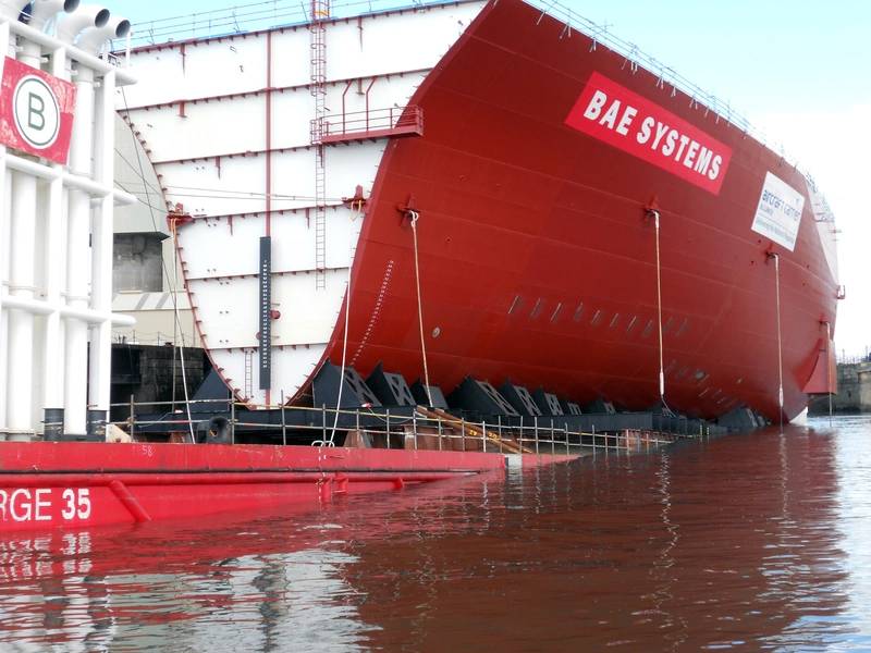 Cradle in situ. Photo Courtesy: Malin Group
Once the groundwork has been carried out a preliminary cradle layout can be created using the knowledge of the required transportations and considering their associated load cases. There are many areas to consider when creating the arrangement and some of the main points are detailed as follows:
- Suitable transport beam width to span support locations in all conditions (build stool, SPMT, and barge grillage extremes)
- Locate suitable strong points on the ship where supports can be positioned, this tends to be in way of bulkheads and frames. Checks should be carried out to ensure hull structure can take loads from supports.
- Determine suitable sizes for cradle beams and sections. High level checks can be carried out initially to give a good steer on the required sizes. These can be refined as more detailed analysis is carried out.
- Consideration should be given to accommodating the weighing arrangement in the design. Adding cross members between transport beams may allow for better weighing positions and reduce the number of load cells required.
- Practicality and feasibility of the design.
Having created a preliminary arrangement this can then be further developed by analysing the design against the previously defined load cases. Detail of the cradle arrangement can be adjusted as required and an iterative design process may take place to further refine the layout. Once complete, the output will be a technically and operationally compliant proposal.
When the cradle design is complete and meets the requirements of the ship transportation it is reasonable to assume that the next step would be to produce the fabrication drawings. However, there may be benefits to be had of involving a third- party at this point to review the design and comment on areas for improvement or concern. This gives added assurance that the design is capable and fit for purpose. Additionally, where transportation cradle design is a relatively new undertaking, it may be useful for a third-party expert to have input during the complete design process to offer guidance and a steer from the outset. This may prevent wasted research and engineering time and result in a better solution at the end. Finally, the detailed drawings of the transportation cradles can be produced and sent for fabrication with the knowledge that the cradles will be suitable for purpose.
In essence, there are many factors to consider when developing a transportation cradle arrangement and a good layout can be key to the success of any ship build and launch project.
- For more information on Malin Abrams, Click Here:
- The Author
 James Ian Bowie, Naval Architect and Team Lead James began his career as a summer intern with Malin Abrams, before gaining a degree in Naval Architecture and joining full time as a graduate. Having successfully worked through the graduate programme he now holds a Naval Architect and Team Lead position. James has experience in a variety of projects from marine heavy lift transportation to design and manufacture of bespoke jigs and has been involved in major site operations worldwide.
