High Performance Skiff Simulations
Aerodynamic and Hydrodynamic CFD Simulations of the High-Performance Skiff R3
Skiffs are high-performance, fast and powerful dinghies designed for onshore racing. An example of Olympic skiff is the well-known 49er. Skiffs have a light displacement, flat hull and an oversized sail-plan, allowing planing with light wind in both upwind and downwind conditions. The typical sail-plan comprises a square top mainsail, a blade jib and a gennaker tacked on the bowsprit. The righting moment is mostly due to the weight of the crew who uses racks and trapezes. In strong breeze and high boat speed conditions, the crew moves aft, lifting the bow out of the water in order to decrease the hydrodynamic drag and improve handling. Conversely, at low boat speeds, the crew moves forward in order to lift the transom out of the water.
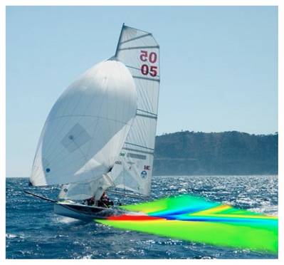
This article presents the results of numerical simulations performed to support the design of the R3 skiff (Figure 1), which was developed for the regatta Mille e una vela per l’università (1001 sails for academia) by the students of the Politecnico di Milano, Italy. In particular, Marco Achler performed the naval architecture analysis as part of his Master Thesis. The competition Mille e una vela per l’università was introduced by Massimo Paperini and Paolo Procesi in 2005 and it has been raced every year since then. It has been promoted by the Università degli Studi Roma Tre until 2010 and by the Università degli Studi di Palermo in 2011 and 2012. The 2013 regatta, Trofeo 1001VELAcup® 2013, was raced in La Spezia. The competing boats must be designed, produced and helmed by undergraduate students. In addition, they must have a maximum length-over-all of 4.60 m and a maximum beam-over-all of 2.10 m, and be able to carry up to 33 m2 of sail area.
The aerodynamic and hydrodynamic forces and moments acting on the boat were modeled separately and then combined into a velocity prediction program (VPP), which allows computing the optimum setup of the boat and the maximum boat speed. Different aerodynamic and hydrodynamic CFD simulations were performed in order to provide input for the VPP.
Hydrodynamic Simulations
For the hydrodynamic model, several CFD simulations were performed to investigate the effect of the longitudinal crew position on the hull resistance. Only half the boat was modeled, taking advantage of its longitudinal symmetry and neglecting the heel angle (the sideways tilting of a boat whilst it sails) and leeway angle (angle between the heading and the water track direction). In fact, skiffs are normally sailed at very low angles of heel, and the high speed allows sailing at low angles of leeway with limited effect on the resistance of the flat hull. A non-conformal grid of about 0.5M hexahedral cells was used. The free surface was modeled using a volume of fluid approach and the boat was free to sink and trim. A range of Froude numbers, Fr, between 0.3 and 1.2 and different longitudinal crew positions were simulated. As an example, Figures 2 and 3 show the free surface elevation at Fr = 0.4 and 1.2, corresponding to a displacement and a planing regime, respectively. Figures 4 and 5 show the skin friction coefficient, Cf, and the net pressure coefficient, Cpnet (hydrostatic pressure coefficient subtracted from the pressure coefficient), for the same two Froude numbers. Figure 6 shows the coefficient of total resistance, Ct, for Froude numbers ranging from 0.3 to 1.2 and for three positions of the longitudinal center of gravity (CG), which ismeasured from the stern and presented in percentage of the boat length. As anticipated, at very low boat speeds (Fr< 0.4) the minimum resistance is achieved with the most forward simulated crew position (CG = 52%), at very high boat speeds (Fr> 1.05) the minimum resistance is achieved with the most aft simulated crew position (CG = 39%), while at intermediate boat speeds the minimum resistance is achieved with an intermediate crew position.
Aerodynamic Simulations
Aerodynamic simulations were performed for different mainsail and jib trims in upwind conditions. The crew plays a significant role in the aerodynamic resistance and thus, hull and crew were modeled together. Figures 7 and 8 show the pressure coefficient, Cp, and a set of streamlines displaying flow velocity. The mesh, consisting of polyhedral cells and a prismatic boundary layer, comprised a total of about 3M cells. The sails were modeled as rigid membranes with zero thickness. Figure 9 shows the lift coefficient, Cl, and drag coefficient, Cd, for the wide range of simulated sail trims. When Cd is plotted versus the square of Cl, the optimum trims collapse on a straight line, where the intercept is the parasitic drag and the slope is inversely proportional to the effective aspect ratio of the combined sail-plan.
The numerical simulations enabled the prediction of the boat speed for different design candidates and permitted to identify the optimum crew position, which drove the design of the deck layout. The boat raced the Mille e una vela per l’università for the first time on 24-27 September 2009 and finished 1st against 14 competitors on that edition. The same platform was used for the following regattas until 2012, when a different platform was designed by a new group of students.
Simone Bartesaghi has a Ph.D in Mechanical Engineering and is a Yacht Designer in Milano, Italy. ([email protected])
simonebartesaghi.com
